Request Quote
Request a quote from Nidec Drive Technology America Corporation.
Request a quote from Nidec Drive Technology America Corporation.
Subscribe to our email newsletter to stay current with our precision gearing solutions, featured products, company updates, and industry news.
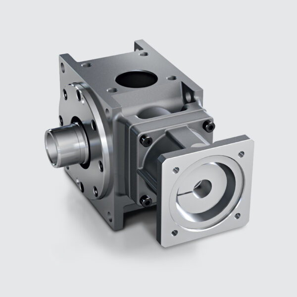
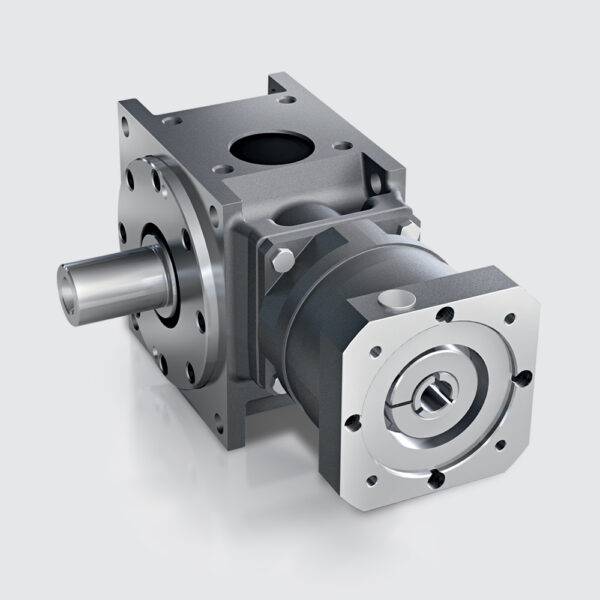
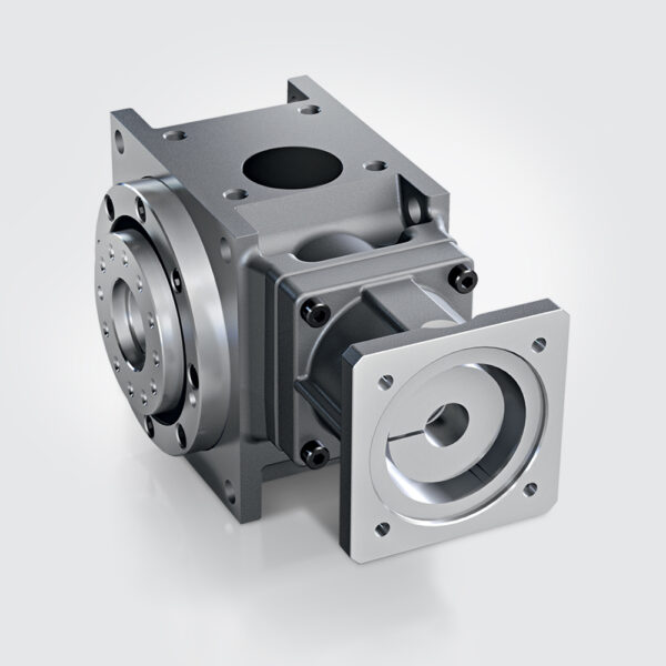
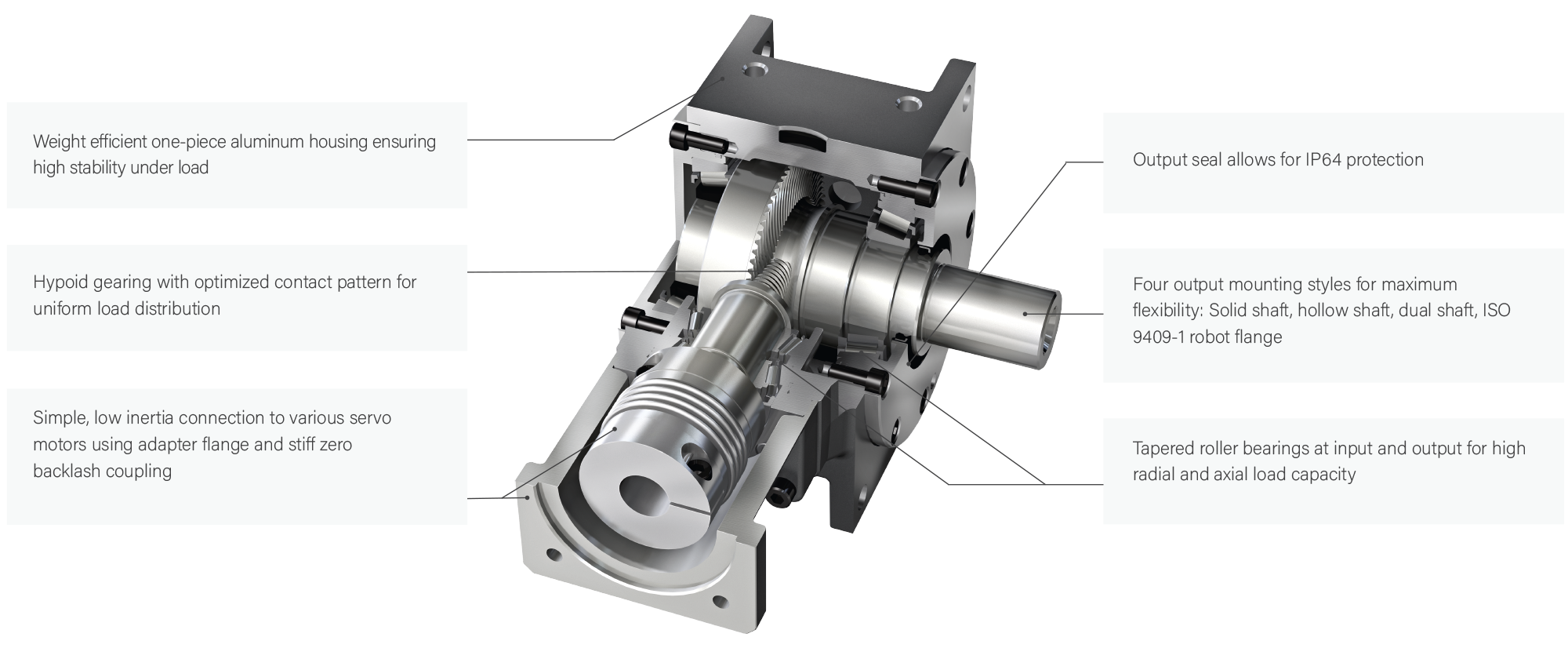
DynaGear is designed for highly dynamic servo applications where precision, efficiency, and compactness are essential. Its optimized hypoid gears ensure smooth, high-torque transfer with minimal backlash of less than 2 arc-min. Tapered roller bearings on both the input and output sides absorb high radial and axial loads, enhancing durability and extending service life. The planetary input stage allows for higher gear ratios, while the lightweight, one-piece aluminum housing provides exceptional stability under load.
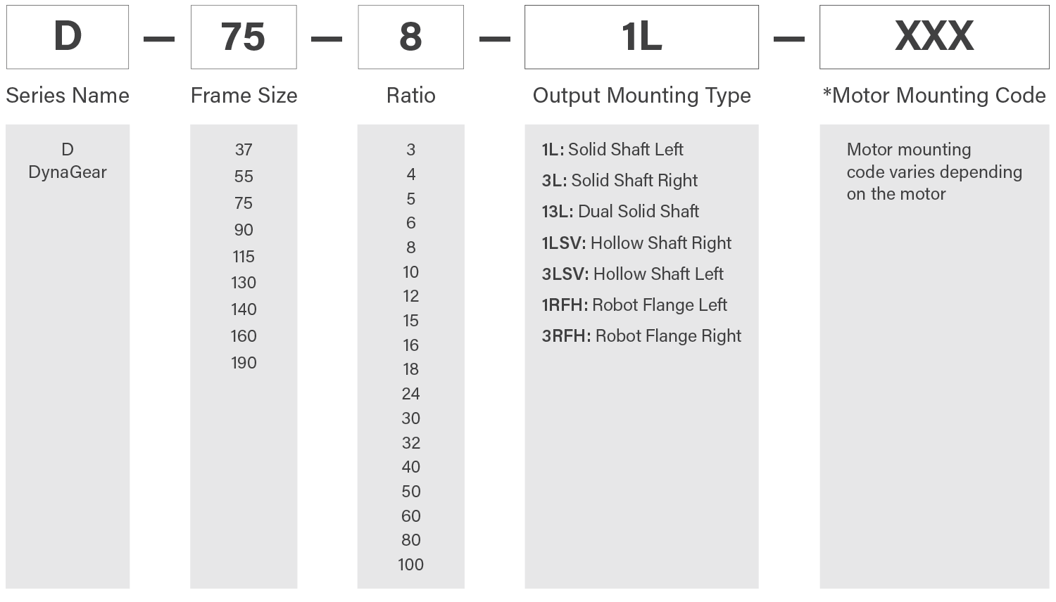
With versatile mounting options, including solid shaft, hollow shaft, dual shaft, and robot flange, DynaGear adapts to various installation needs. Its maintenance-free, lifetime lubrication ensures reliable operation, and its compact design saves valuable space in constrained environments.
| Frame Size | Units | Note | 37 | 55 | 75 | 90 | 115 | 130 | 140 | 160 | 190 |
| Nominal Output Torque | T2N [Nm] | *1 | 22 | 35 | 70 | 140 | 260 | 430 | 720 | 1100 | 1440 |
| Maximum Acceleration Torque | T2B [Nm] | *2 | 33 | 53 | 105 | 210 | 390 | 645 | 1080 | 1650 | 2160 |
| Emergency Stop Torque | T2Not [Nm] | *3 | 44 | 70 | 140 | 280 | 520 | 860 | 1440 | 2200 | 2880 |
| Nominal Input Speed (Ratios 3/4/5) | n1N [rpm] | *4 | 2300 | 2100 | 1800 | 1500 | 1150 | 1000 | 700 | 600 | 550 |
| Nominal Input Speed (Ratios 6/8/10) | n1N [rpm] | *4 | 3700 | 3200 | 2700 | 2200 | 1800 | 1500 | 1200 | 1100 | 1000 |
| Maximum Input Speed | n1max [rpm] | *5 | 8000 | 8000 | 8000 | 7000 | 6000 | 5000 | 5000 | 4500 | 4500 |
| Maximum Radial Load | F2Rmax [N] | *6 | 2200 | 3300 | 4900 | 7200 | 10000 | 12600 | 15000 | 18000 | 22500 |
| Maximum Axial Load | F2Amax [N] | *7 | 1100 | 1650 | 2450 | 3600 | 5000 | 6300 | 7500 | 9000 | 11250 |
| Efficiency | h [%] | *8 | > 96 | > 96 | > 96 | > 96 | > 96 | > 96 | > 96 | > 96 | > 96 |
| Torsional Rigidity | Ct21 [Nm/arcmin] | *9 | 1.3 | 2.1 | 4.2 | 10.5 | 23.4 | 39.6 | 61.8 | 90 | 126 |
| Maximum Torsional Backlash (Standard) | jt [arcmin] | *10 | > 5 | ≤5 | ≤5 | ≤4 | ≤4 | ≤4 | ≤4 | ≤4 | ≤4 |
| Maximum Torsional Backlash (Reduced) | jt [arcmin] | *10 | - | - | ≤ 3 | ≤2 | ≤2 | ≤2 | ≤2 | ≤2 | ≤2 |
| Noise Level | LpA [dB(A)] | *11 | > 65 | > 66 | > 66 | > 68 | > 68 | > 70 | > 70 | > 72 | > 72 |
| Ambient Temperature | [°C] | - | -10 to 90 | -10 to 90 | -10 to 90 | -10 to 90 | -10 to 90 | -10 to 90 | -10 to 90 | -10 to 90 | -10 to 90 |
| Permitted Housing Temperature | [°C] | - | 90 | 90 | 90 | 90 | 90 | 90 | 90 | 90 | 90 |
| Protection Class | - | - | IP64 | IP64 | IP64 | IP64 | IP64 | IP64 | IP64 | IP64 | IP64 |
| Service Life | SL [h] | *12 | 30,000 | 30,000 | 30,000 | 30,000 | 30,000 | 30,000 | 30,000 | 30,000 | 30,000 |
| Weight | m [kg] | - | 1.9 | 3.5 | 5.5 | 9.5 | 15.5 | 23.5 | 32.5 | 46.5 | 60 |
* Lubrication: Synthetic Oil [ISO VG-Class 150]
| Frame Size | Units | Note | 37 | 55 | 75 | 90 | 115 | 130 | 140 | 160 | 190 |
| Nominal Output Torque | T2N [Nm] | *1 | 15 | 25 | 50 | 95 | 180 | 300 | 510 | 815 | 1020 |
| Maximum Acceleration Torque | T2B [Nm] | *2 | 22 | 38 | 75 | 143 | 270 | 450 | 765 | 1223 | 1530 |
| Emergency Stop Torque | T2Not [Nm] | *3 | 30 | 50 | 100 | 190 | 360 | 600 | 1020 | 1630 | 2040 |
| Nominal Input Speed | n1N [rpm] | *4 | 4500 | 3900 | 3300 | 2800 | 2300 | 2000 | 1600 | 1350 | 1300 |
| Maximum Input Speed | n1max [rpm] | *5 | 8000 | 8000 | 8000 | 7000 | 6000 | 5000 | 5000 | 4500 | 4500 |
| Maximum Radial Load | F2Rmax [N] | *6 | 2200 | 3300 | 4900 | 7200 | 10000 | 12600 | 15000 | 18000 | 22500 |
| Maximum Axial Load | F2Amax [N] | *7 | 1100 | 1650 | 2450 | 3600 | 5000 | 6300 | 7500 | 9000 | 11250 |
| Efficiency | h [%] | *8 | > 93 | > 93 | > 93 | > 93 | > 93 | > 93 | > 93 | > 93 | > 93 |
| Torsional Rigidity | Ct21 [Nm/arcmin] | *9 | 1.3 | 2.1 | 4.2 | 10.5 | 23.4 | 39.6 | 61.8 | 90 | 126 |
| Maximum Torsional Backlash (Standard) | jt [arcmin] | *10 | > 5 | ≤5 | ≤5 | ≤4 | ≤4 | ≤4 | ≤4 | ≤4 | ≤4 |
| Maximum Torsional Backlash (Reduced) | jt [arcmin] | *10 | - | - | ≤ 3 | ≤2 | ≤2 | ≤2 | ≤2 | ≤2 | ≤2 |
| Noise Level | LpA [dB(A)] | *11 | > 65 | > 66 | > 66 | > 68 | > 68 | > 70 | > 70 | > 72 | > 72 |
| Ambient Temperature | [°C] | - | -10 to 90 | -10 to 90 | -10 to 90 | -10 to 90 | -10 to 90 | -10 to 90 | -10 to 90 | -10 to 90 | -10 to 90 |
| Permitted Housing Temperature | [°C] | - | 90 | 90 | 90 | 90 | 90 | 90 | 90 | 90 | 90 |
| Protection Class | - | - | IP64 | IP64 | IP64 | IP64 | IP64 | IP64 | IP64 | IP64 | IP64 |
| Service Life | SL [h] | *12 | 30,000 | 30,000 | 30,000 | 30,000 | 30,000 | 30,000 | 30,000 | 30,000 | 30,000 |
| Weight | m [kg] | - | 1.9 | 3.5 | 5.5 | 9.5 | 15.5 | 23.5 | 32.5 | 46.5 | 60 |
* Lubrication: Synthetic Oil [ISO VG-Class 150]
| Frame Size | Units | Note | - | 55 | 75 | 90 | 115 | 130 | 140 | 160 | 190 |
| Nominal Output Torque | T2N [Nm] | *1 | - | 35 | 70 | 140 | 260 | 430 | 720 | 1100 | 1440 |
| Maximum Acceleration Torque | T2B [Nm] | *2 | - | 53 | 105 | 210 | 390 | 645 | 1080 | 1650 | 2160 |
| Emergency Stop Torque | T2Not [Nm] | *3 | - | 70 | 140 | 280 | 520 | 860 | 1440 | 2200 | 2880 |
| Nominal Input Speed | n1N [rpm] | *4 | - | 3500 | 3000 | 3000 | 2500 | 2500 | 2500 | 2500 | 2500 |
| Maximum Input Speed | n1max [rpm] | *5 | - | 6000 | 6000 | 6000 | 6000 | 5000 | 5000 | 4500 | 4500 |
| Maximum Radial Load | F2Rmax [N] | *6 | - | 3300 | 4900 | 7200 | 10000 | 12600 | 15000 | 18000 | 22500 |
| Maximum Axial Load | F2Amax [N] | *7 | - | 1650 | 2450 | 3600 | 5000 | 6300 | 7500 | 9000 | 11250 |
| Efficiency | h [%] | *8 | - | > 92 | > 92 | > 92 | > 92 | > 92 | > 92 | > 92 | > 92 |
| Torsional Rigidity | Ct21 [Nm/arcmin] | *9 | - | 2.1 | 4.1 | 10.2 | 22.8 | 37.8 | 60.1 | 86.5 | 119.2 |
| Maximum Torsional Backlash (Standard) | jt [arcmin] | *10 | - | ≤7 | ≤7 | ≤6 | ≤6 | ≤6 | ≤6 | ≤6 | ≤6 |
| Maximum Torsional Backlash (Reduced) | jt [arcmin] | *10 | - | ≤5 | ≤5 | ≤3 | ≤3 | ≤3 | ≤3 | ≤3 | ≤3 |
| Noise Level | LpA [dB(A)] | *11 | - | > 66 | > 66 | > 68 | > 68 | > 70 | > 70 | > 72 | > 72 |
| Ambient Temperature | [°C] | - | -10 to 90 | -10 to 90 | -10 to 90 | -10 to 90 | -10 to 90 | -10 to 90 | -10 to 90 | -10 to 90 | -10 to 90 |
| Permitted Housing Temperature | [°C] | - | 90 | 90 | 90 | 90 | 90 | 90 | 90 | 90 | 90 |
| Protection Class | - | - | IP64 | IP64 | IP64 | IP64 | IP64 | IP64 | IP64 | IP64 | IP64 |
| Service Life | SL [h] | *12 | 30,000 | 30,000 | 30,000 | 30,000 | 30,000 | 30,000 | 30,000 | 30,000 | 30,000 |
| Weight | m [kg] | - | - | 4 | 6.5 | 12.5 | 19.5 | 27 | 36 | 49 | 61.5 |
* Lubrication: Synthetic Oil [ISO VG-Class 150], DIN 51818 Synthetic Grease
| Frame Size | 37 | 55 | 75 | 90 | 115 | 130 | 140 | 160 | 190 |
| 3:1 Ratio | 0.178 | 0.39 | 0.98 | 2.42 | 7.12 | 14.03 | 26.96 | 52.32 | 91.47 |
| 4:1 Ratio | 0.14 | 0.30 | 0.73 | 1.77 | 5.09 | 9.17 | 17.44 | 32.78 | 62.43 |
| 5:1 Ratio | 0.123 | 0.23 | 0.58 | 1.41 | 4.00 | 7.12 | 13.53 | 24.76 | 44.29 |
| 6:1 Ratio | 0.113 | 0.22 | 0.52 | 1.41 | 3.65 | 6.76 | 12.25 | 22.49 | 39.55 |
| 8:1 Ratio | 0.104 | 0.17 | 0.43 | 1.12 | 2.85 | 5.09 | 8.95 | 15.67 | 27.07 |
| 10:1 Ratio | 0.099 | 0.15 | 0.38 | 1.00 | 2.46 | 4.27 | 7.38 | 12.47 | 21.43 |
| 12:1 Ratio | 0.097 | 0.14 | 0.36 | 0.88 | 2.25 | 3.81 | 6.47 | 10.67 | 18.14 |
| 15:1 Ratio | 0.095 | 0.13 | 0.34 | 0.81 | 2.07 | 3.45 | 5.76 | 9.23 | 15.53 |
| 16:1 Ratio | - | 0.40 | 1.19 | 1.25 | 5.12 | 5.37 | 8.74 | 9.70 | 11.55 |
| 18:1 Ratio | - | 0.46 | 1.38 | 1.41 | 6.64 | 6.73 | 12.57 | 12.85 | 13.33 |
| 24:1 Ratio | - | 0.39 | 1.15 | 1.18 | 4.9 | 4.99 | 7.99 | 8.27 | 8.75 |
| 30:1 Ratio | - | 0.37 | 1.06 | 1.09 | 4.15 | 4.24 | 6.58 | 6.86 | 7.34 |
| 32:1 Ratio | - | 0.38 | 1.15 | 1.16 | 4.84 | 4.88 | 7.79 | 7.89 | 8.07 |
| 40:1 Ratio | - | 0.36 | 1.06 | 1.07 | 4.09 | 4.13 | 6.38 | 6.48 | 6.66 |
| 50:1 Ratio | - | 0.36 | 1.05 | 1.06 | 4.07 | 4.09 | 6.31 | 6.36 | 6.45 |
| 60:1 Ratio | - | 0.35 | 0.94 | 0.97 | 3.20 | 3.29 | 4.14 | 4.42 | 4.90 |
| 80:1 Ratio | - | 0.34 | 0.94 | 0.95 | 3.14 | 3.18 | 3.94 | 4.04 | 4.22 |
| 100:1 Ratio | - | 0.34 | 0.93 | 0.94 | 3.12 | 3.14 | 3.87 | 3.92 | 4.01 |
| Maximum Motor Acceleration Torque | T1BMot | Nm |
| Nominal Output Torque | T2N | Nm |
| Maximum Acceleration Torque | T2B | Nm |
| Emergency Stop Torque | T2Not | Nm |
| Nominal Input Speed | n1N | rpm |
| Maximum Input Speed | n1max | rpm |
| Maximum Input Radial Load | F1Rmax | N |
| Maximum Output Radial Load | F2Rmax | N |
| Maximum Input Axial Load | F1Amax | N |
| Maximum Output Axial Load | F2Amax | N |
| Mass Moment of Inertia | l1 | kgcm² |
| Efficiency at Full Load | η | % |
| Torsional Rigidity | Ct21 | Nm/arc-min |
| Maximum Torsional Backlash | jt | arc-min |
| Noise Level | LpA | dB (A) |
| Protection Class | Lh | h |
| Run time | RT | min |
| Duty cycle | DC | % |
| Ambient Temperature | ta | °C |
| Thermal Performance Limit | Ptherm | kW |
| Performance | P | kW |
| Weight | m | kg |
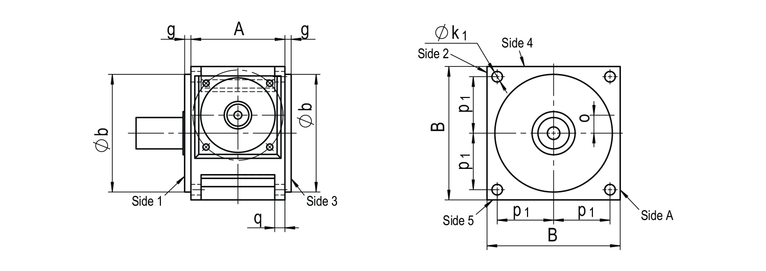
| Frame Size | A | B | Ø b g6 | g | o | p1 | p2 | Ø k1 | k2 | q |
| 37 | 56 | 75 | 74 | 11 | 7.5 | 31 | 21 | 6.6 | M6 | - |
| 55 | 60 | 90 | 89 | 13.5 | 9 | 39 | 22 | 6.6 | M6 | 8 |
| 75 | 80 | 115 | 105 | 8.5 | 14 | 49 | 27 | 9 | M8 | 10 |
| 90 | 100 | 140 | 125 | 8 | 18 | 59 | 33 | 11 | M10 | 11 |
| 115 | 120 | 170 | 150 | 8 | 23 | 72 | 40 | 13.5 | M12 | 13 |
| 130 | 138 | 192 | 173 | 10 | 27 | 82 | 48 | 13.5 | M12 | 14 |
| 140 | 146 | 215 | 195 | 10 | 32 | 91 | 52 | 17.5 | M16 | 15 |
| 160 | 166 | 240 | 225 | 10 | 38 | 103 | 60 | 17.5 | M16 | 16 |
| 190 | 196 | 260 | 245 | 10 | 42 | 112 | 70 | 17.5 | M16 | 17 |
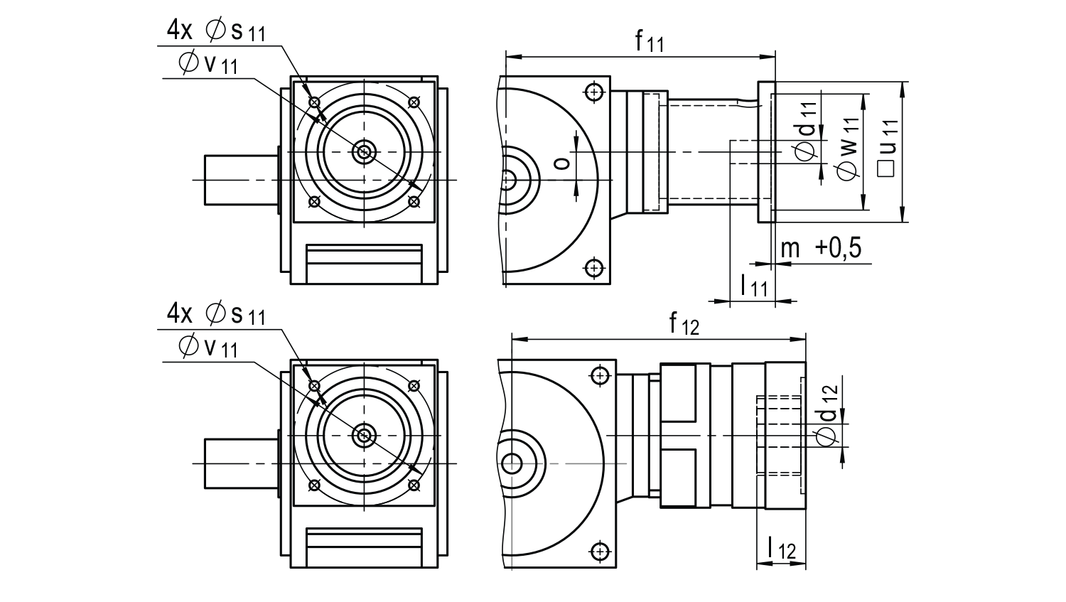
| Frame Size | Ø d11 x l11 | Ø d11 x l11 | Ø d11 x l11 | □u x f11 | □u x f11 | □u x f11 |
| 37 | 9x23 | 11x26 | - | 55x127.5 | 70x127.5 | - |
| 55 | 9x23 | 11x26 | 14x30 | 55x130 | 75x140 | - |
| 78 | 11x26 | 14x30 | 19x40 | 75x168 | 90x168 | 90x180 |
| 90 | 14x30 | 19x40 | 24x50 | 90x191 | 115x191 | 115x201 |
| 115 | 19x40 | 24x50 | 32x60 | 115x220 | 140x220 | 140x235 |
| 130 | 24x50 | 32x60 | 38x80 | 140x245 | 190x245 | 190x260 |
| 140 | 24x50 | 32x60 | 38x80 | 140x260 | 190x260 | 190x280 |
| 160 | 32x60 | 38x80 | 48x80 | 140x298 | 190x308 | 260x308 |
| 190 | 32x60 | 38x80 | 48x80 | 190x335 | 260x345 | - |
| Frame Size | Ø d12 x l12 x f12 | Ø d12 x l12 x f12 | Ø d12 x l12 x f12 | Ø d12 x l12 x f12 |
| 37 | - | - | - | - |
| 55 | 9x25x158.1 | 9x25x158.1 | 14x30x168.1 | - |
| 78 | 14x30x198.1 | 16x30x198.1 | 19x40x198.6 | 24x50x206.6 |
| 90 | 14x30x214.1 | 16x30x214.1 | 19x40x214.1 | 24x50x222.6 |
| 115 | 19x40x246.5 | 24x50x255.5 | 32x60x255.5 | - |
| 130 | 19x40x263.5 | 24x50x272.5 | 32x60x272.5 | - |
| 140 | 24x50x297.8 | 32x60x302.8 | 38x80x322.8 | - |
| 160 | 24x50x317.8 | 32x60x322.8 | 38x80x342.8 | - |
| 190 | 24x50x336.8 | 32x60x341.8 | 38x80x361.8 | - |
* Above input dimensions are for reference only and depend on motor dimensions. Contact us to configure the appropriate adaptation for your specific motor.
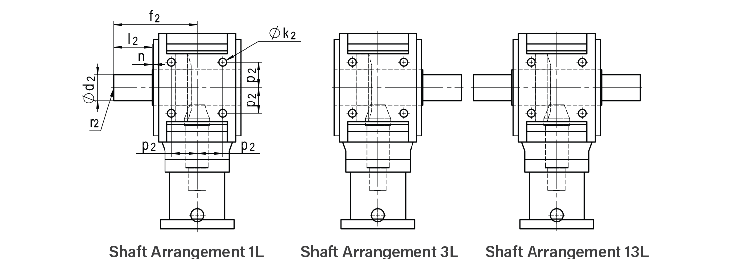
| Frame Size | Ø d2 k6 | l2 | f2 | n | r2 |
| 37 | 16 | 25 | 65 | 1 | M5 |
| 55 | 20 | 35 | 80 | 1.5 | M6 |
| 75 | 24 | 40 | 90 | 1.5 | M8 |
| 90 | 32 | 50 | 110 | 2 | M12 |
| 115 | 40 | 60 | 130 | 2 | M16 |
| 130 | 48 | 75 | 156 | 2 | M16 |
| 140 | 55 | 90 | 175 | 2 | M20 |
| 160 | 60 | 100 | 195 | 2 | M20 |
| 190 | 70 | 110 | 220 | 2 | M20 |
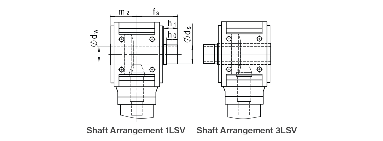
| Frame Size | Ø dw H7 | Ø ds f7 | h0 | h1 | fs | m2 |
| 37 | 16 | 20 | 20 | 25 | 66 | 40 |
| 55 | 20 | 24 | 20 | 25 | 71.5 | 45 |
| 75 | 25 | 30 | 22 | 27 | 79.5 | 50 |
| 90 | 30 | 36 | 26 | 31 | 93 | 60 |
| 115 | 40 | 50 | 29 | 34 | 107 | 70 |
| 130 | 48 | 55 | 32 | 37 | 121 | 81 |
| 140 | 55 | 68 | 32 | 38 | 127 | 85 |
| 160 | 60 | 75 | 34 | 41 | 139 | 95 |
| 190 | 70 | 80 | 34 | 41 | 159 | 110 |
*1 Hollow output shaft arrangements 1LSV/3LSV include extended shaft for shrink disc. Shrink disc sold separately.
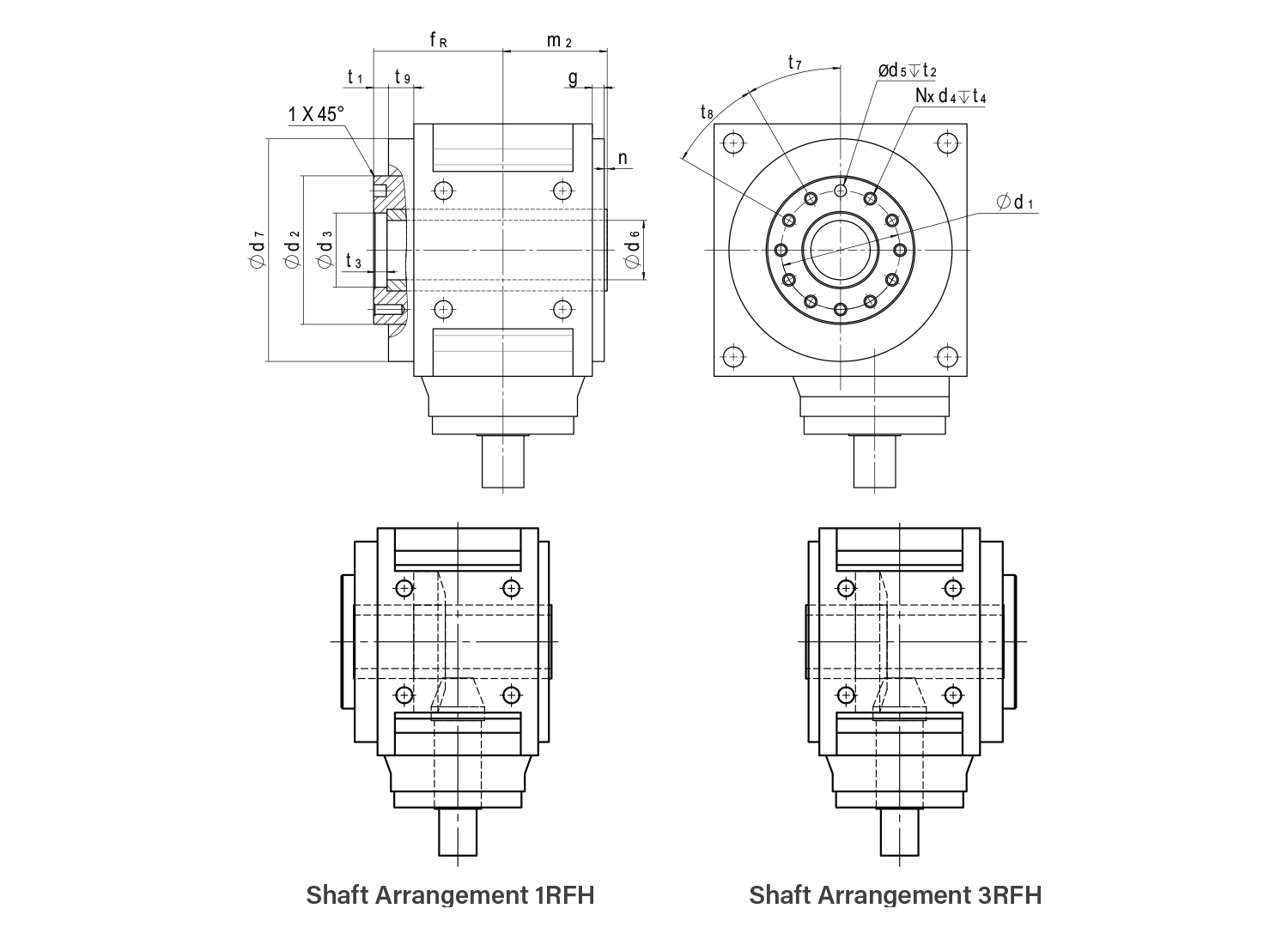
| Frame Size | Ø d1 | Ø d2 h8 | Ø d3H7 | d4 | Ø d5H7 | Ø d6 | Ø d7 | fR | m2 |
| 55 | 40 | 50 | 25 | M6 | 6 | 18 | 89 | 57 | 45 |
| 75 | 50 | 63 | 31.5 | M6 | 6 | 24 | 105 | 62.5 | 50 |
| 90 | 63 | 80 | 40 | M6 | 6 | 28 | 125 | 73 | 60 |
| 115 | 80 | 100 | 50 | M8 | 8 | 40 | 150 | 87 | 70 |
| 130 | 80 | 100 | 50 | M8 | 8 | 40 | 173 | 96.5 | 81 |
| 140 | 100 | 125 | 63 | M8 | 8 | 52 | 195 | 100.5 | 85 |
| 160 | 100 | 125 | 63 | M8 | 8 | 52 | 225 | 115 | 95 |
| 190 | 125 | 160 | 80 | M10 | 10 | 65 | 245 | 132.5 | 110 |
| Frame Size | g | n | t1 | t2 | t3 | t4 | t7 | t8 | t9 | N |
| 55 | 13.5 | 1.5 | 7 | 6.5 | 7 | 1.5 x d4 | 45° | 45° | 20 | 7 |
| 75 | 8.5 | 1.5 | 7 | 6.5 | 7 | 1.5 x d4 | 45° | 45° | 15.5 | 7 |
| 90 | 8 | 2 | 7 | 6.5 | 7 | 1.5 x d4 | 45° | 45° | 16 | 7 |
| 115 | 8 | 2 | 10 | 8.5 | 8.5 | 1.5 x d4 | 30° | 30° | 17 | 11 |
| 130 | 10 | 2 | 10 | 8.5 | 8.5 | 1.5 x d4 | 30° | 30° | 17.5 | 11 |
| 140 | 10 | 2 | 10 | 8.5 | 8.5 | 1.5 x d4 | 30° | 30° | 17.5 | 11 |
| 160 | 10 | 2 | 12 | 8.5 | 8.5 | 1.5 x d4 | 30° | 30° | 20 | 11 |
| 190 | 10 | 2 | 12 | 10.5 | 8.5 | 1.5 x d4 | 30° | 30° | 22.5 | 11 |